How to Calculate Battery Total Voltage in series Battery Connection ?

How to Calculate Battery Total Voltage in series Battery Connection ?

How to wire batteries in series:

The series connection is the one of the type of battery connection. Series connections of batteries will change in voltage rating, but the current will be stay the same.

What is a series connection of battery?

The current is the same through each component regardless of what components are used or their values in series connection. The voltage drops across each component in the circuit are dependent upon the values of the components used in the circuit

Question:

How to Calculate Battery Total Voltage in series Battery Connection ?


Solution:

As per previous description voltage will be the change and current will be the remains same battery series connection.

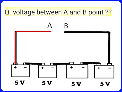
Here we have 5 volt battery voltage of each battery and we need to find total voltage of this series connected batteries, means voltage between point A and B.

In a series circuit share the same current: I Total = I1 + I2 + . . . +In

The sum of the individual resistances: R Total = R1 + R2 + . . . Rn

Total Sum of the individual voltage drops E Total = E1 + E2 + . . . En

Important Note For Solution

  • Total Voltage is equal to sum of the individual battery voltage.
Now we Go for the solution of the question

Total Voltage V= sum of individual voltage of battery
                         V= V1 + V2 + V3 + V4

                         V= 5 + 5 + 5 + 5

                         V= 20 volt


Or we can also solve this question by using another method which is describe below:

This method is applicable when the each battery voltage will be the same. So in this case all the battery voltage would be the same.

Total Voltage V = No. Of Batteries × Individual Battery voltage
  
                            = 4 × 5

                        V = 20 volt

So Final Answer is Total Voltage V = 20 volt


How to Calculate Battery Total Voltage and Total Capacity in Parallel Battery Connection ?

How to calculate Total Voltage and Total Capacity in Parallel Battery Connection?

How to wire batteries in parallel:

The parallel connection is the one of the type of battery connection. Parallel connections of batteries will increase your current rating, but the voltage will be stay the same.

Question:

How to Calculate Battery Total Voltage and Total Capacity in Parallel Battery Connection ?

Solution:

Here we connected 4 batteries in parallel and each have 125Ah capacity and each have 12v battery voltage.

As per description "Parallel connections of batteries will increase your current rating, but the voltage will be stay the same."

Formula for Parallel Battery Connection

If each battery voltage is same,

Total Voltage = Same of Each battery voltage

Total Battery Capacity= No. Of Batteries × Capacity of each Battery

So as per Formula,

We have 4 batteries connected in parallel and each have same ratings that it has 125Ah battery capacity and each have 12v voltage.

So,
Total Voltage V = Same of Each battery voltage
                             = 12v

Total Capacity  = No. Of Batteries × Capacity of each Battery
                            = 4 × 125
                            = 500 Ah

So our Final Answers are

  • Total Voltage V = 12v
  • Total Capacity  = 500Ah

To join batteries in parallel connection, we should use a jumper wire to connect both the positive terminals and other jumper wire to connect both the negative terminals of both batteries to each other.

Here connection should be done Negative to negative and positive to positive.

Here we can connect our load to one of the batteries, and it will drain all equally.

However, the best suitable method for keeping the batteries equalized is to connect to the positive at one end of connection of the battery pack, and the negative at the other end of connection to the pack.

It is also possible to connect batteries in series and parallel connection or configuration. By this way we can increase our voltage output and Amp/Hour rating. 
How Stepper Motor Works?? | Electrical Machine Theory

How Stepper Motor Works?? |  Electrical Machine Theory


Here we provided theory of stepper motor and also explain it's working principle and how stepper motor works, this theory is more useful for learning in electrical machine theory.

How Stepper Motor Works?? |  Electrical Machine Theory


Stepper Motor

A stepper motor is an incremental motion machine or the motor which turns in discrete movement called the step.

It does not rotate continuously as a conventional motor does.

The stepper motor is a special type of synchronous motor which is designed to rotate through a specific number of degrees for each electrical pulse received by its control unit.

Typical steps are 20, 2.5 ,5 ,7.5 and 15 per pulse. These motors are built to follow signals as rapid as 1200 pulses per second and with equivalent power ratings up to several kW.

The stepper motor is used in digitally controlled position control system in open loop mode.

The input command is in the form of a train of pulses to turn a shaft through a specified angel.


Advantages of stepper Motor:

The stepper motor is having the following advantages:

  • Compatibility with digital systems.
  • The angular displacement can be precisely 
  • controlled without any feedback arrangement.
  • No sensors are needed for position and speed sensing.
  • It can be readily interfaced with microprocessor or computer based microcontroller.

Stepper Motor Types :


There are three main types of stepper motor types,

  • Permanent magnet stepper
  • Hybrid synchronous stepper
  • Variable reluctance stepper


Applications of Stepper Motor:

Stepper motors have a many applications, which is mentioned below:

  1. ✓Paper feed motors in typewriters and printers.
  2. ✓Positioning of print heads.
  3. ✓Pens in XY-plotters.
  4. ✓Recording heads in computer disc drives.
  5. ✓Positioning of worktables and tools in numerically controlled machining equipment.
  6. ✓Also employed to perform many other functions such as metering, mixing; cutting, blending, stirring etc. in several commercial, military and medical applications.

Electrical Engineering Interview Questions

Electrical Engineering Interview Questions

Electrical Engineering Interview Questions


Hello guys, welcome back to our blog Electrical Engineering. Here we today discuss about mostly asked Electrical Engineering Interview Questions.

In this article we list the basic question related to activate elements and passive elements. Here we mostly covered all the mcq's related to activate and passive elements. If any element is not considered in the question then you can list out it in comment section.

Basic Electrical Engineering Interview Questions Related to Activate Elements and Passive elements:


What is the Function Of Transformer?

A. Step Up Voltage
B. Step Down Voltage
C. A & B Both
D. None of these

Answer: C. A & B Both

(1) Resistance is which type of element?

A. Passive Element
B. Active Element
C. Active and Passive Both
D. None of the Above

  • Answer: A. Passive Element


(2) Capacitor is which type of element?

A. Passive Element
B. Active Element
C. Active and Passive Both
D. None of the Above

  • Answer: A. Passive Element


(3) Diode is which type of element?

A. Passive Element
B. Active Element
C. Active and Passive Both
D. None of the Above

  • Answer: B. Active Element


(4) Transistor is which type of element?

A. Passive Element
B. Active Element
C. Active and Passive Both
D. None of the Above

  • Answer: B. Active Element


(5) Thermistor is which type of element?

A. Passive Element
B. Active Element
C. Active and Passive Both
D. None of the Above

  • Answer: B. Active Element


(6) Inductor is which type of element?

A. Passive Element
B. Active Element
C. Active and Passive Both
D. None of the Above

  • Answer: A. Passive Element


(7) Battery is which type of element?

A. Passive Element
B. Active Element
C. Active and Passive Both
D. None of the Above

Answer: B. Active Element


(8) Transformer is which type of element?

A. Passive Element
B. Active Element
C. Active and Passive Both
D. None of the Above

  • Answer: A. Passive Element

(9) LED is which type of element?

A. Passive Element
B. Active Element
C. Active and Passive Both
D. None of the Above

  • Answer: B. Active Element


(10) Thermistor is which type of element?

A. Passive Element
B. Active Element
C. Active and Passive Both
D. None of the Above

  • Answer: A. Passive Element


Gas Turbine Power Plant With Simple Layout

Gas Turbine Power Plant With Simple Layout


The simplest gas turbine power plant layout and basic information of it is described in this article. This is the general layout of gas turbine power plant. All the description is described below in detail.

Gas Turbine Power Plant With Simple Layout


A gas turbine plant may be defined as a plant in which the principal prime-mover is of the turbine type and the working medium is permanent gas.


A simple gas turbine plant consists  the following below equipment:


✓Turbine.

✓A compressor mounted on the same shaft or coupled to the turbine.

✓The combustor.

✓Auxiliaries such as starting device, auxiliary lubrication pump, fuel system, oil system and
the duct system etc.


A modified plant may have in addition to above an intercooler, regenerator, a preheater etc.


The working fluid is compressed in a compressor which is generally rotary, multistage type.


Heat energy is added to the compressed fluid in the combustion chamber.


This high energy fluid, at high temperature and pressure, then expands in the turbine unit thereby generating slower.


Part of the power generated is consumed in driving the generating compressor and accessories and the rest is utilized in electrical energy.


The gas turbines work on open cycle, semi-closed cycle or closed cycle.


In order to improve efficiency, compression and expansion of working fluid is carried out in multi-stages.

Gas Turbine Power Plant Advantages :


Construction wise a gas turbine power plant is much simpler than a steam turbine power plant.

Gas turbine power plant is smaller than that of a steam turbine power plant.

It does not have any boiler like component. So, the accessories associated with the boiler are absent here.

It does not deal with steam. So, it does not require any condenser.

A gas turbine power plant can more instantly be started than an equivalent steam turbine power plant.

How to Check Connection is Star or Delta?

How to Check Connection is Star or Delta?


How to check connection is Star or Delta
How to check connection is Star or Delta?

Here we explain that how to check connection is Star or Delta. Now we go for explanation.

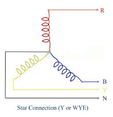
To know the connection is Star or Delta, Firstly we know that the circuit Diagram of star connection and Delta connection.

Below we saw the circuit diagram of star connection and circuit Diagram Of Delta Connection.

Circuit Diagram Of Star Connection:

Circuit Diagram Of Star Connection


Circuit Diagram Of Delta Connection:

Circuit Diagram Of Delta Connection


So Now you can identify the connection Star or Delta by using circuit Diagram Of Star Connection and circuit Diagram Of Delta Connection.

Difference Between Star Connection and Delta connection:

So, Now we can see the difference between connection of Star and Delta. So, by using this comparison you can definitely identify the connection is Star or Delta.

  • Star Connection is a 4 – wire connection and Delta Connection is a 3 – wire connection.
  • Star Point is the Common point of the Star Connection And In Delta Connection There is no neutral. 
  • In Star Connection Line Voltage and Phase Voltage is different. In Delta connection Line Voltage and Phase Voltage are same.
  • Line Current and Phase Current are same in Star Connection. Line current is root three times the phase current in Delta connection.
  • In Star Connection, IL = IP. Delta connection, IL = √3 IP.

Here In Below image we saw the difference between Star Connection and Delta connection

Difference between star and Delta connection
Difference between Star and Delta connection

So,I hope You understand all the difference and Circuit Diagram Of Star Connection and Circuit Diagram Of Delta Connection.

Right Or Wrong?? Can You Give Answer?

 Right Or Wrong?? Can You Give Answer? 


Are You Electrical Engineer?? If Yes Then Give Answer This Image Is Right Or Wrong??? 


What's Wrong On This Picture???

What's Wrong On This Picture??? 


Are You Engineer? Than Tell Me What is Wrong On this Below Picture 

Why Are Salt & Charcoal Added in Earthing Pit??

Why Are Salt & Charcoal Added in Earthling Pit?? 


Answer :

Coal or Charcoal is made of carbon which is good conductor which can minimize the earth resistance. 

The salt is use as electrolyte to form conductivity between the  earth electrode Coal and Earth with humidity. 

Sand has been used to form porosity to cycle water and humidity around the mixture.

The main purpose of providing earthling is to discharge the leakage current or the fault current safely to the ground. 

That Means better conductivity of the soil or lesser its resistance. So Adding charcoal and water in earthling pit which can decreases soil resistivity. 

The layer of charcoal and salt helps to maintain low resistance path for earth fault currents. 

Because of ionic behavior of the salt and charcoal they will be maintain moisture content all around the earth pit. 

How much charcoal and salt is used in earthing?


31 ratio of charcoal & salt used in one earth pit for good result. Our charcoal is highly acclaimed in electrical uses that are used along with salt for earthing ,which gives a temporary solution for getting low resistivity.

What is the good earthing value?


Ideally a ground resistance should be of zero ohms. There is not one standard ground resistance. The NFPA and IEEE have advices that a ground resistance value of 5.0 ohms or less.

Which is the best earthing?


Plate earthing is the best earthing.

Which of the following is used in earth pit?


Salt and charcoal are added in the earth pit for improving conductivity.

How many kg of salt and charcoal is used in pipe earthing?


The amount of charcoal and salt needed for GI pipe earthing are 10 Kg and 10 Kg respectively.

So, due to this reason Salt & Charcoal Added in Earthing Pit.

Basic Electrical Formulas

Basic Electrical Formulas

Here Presented Best Basic Electrical Formulas For Electrical Engineer For Help in Improve Knowledge in Field Of Electrical Engineering.