How Stepper Motor Works?? | Electrical Machine Theory

How Stepper Motor Works?? |  Electrical Machine Theory


Here we provided theory of stepper motor and also explain it's working principle and how stepper motor works, this theory is more useful for learning in electrical machine theory.

How Stepper Motor Works?? |  Electrical Machine Theory


Stepper Motor

A stepper motor is an incremental motion machine or the motor which turns in discrete movement called the step.

It does not rotate continuously as a conventional motor does.

The stepper motor is a special type of synchronous motor which is designed to rotate through a specific number of degrees for each electrical pulse received by its control unit.

Typical steps are 20, 2.5 ,5 ,7.5 and 15 per pulse. These motors are built to follow signals as rapid as 1200 pulses per second and with equivalent power ratings up to several kW.

The stepper motor is used in digitally controlled position control system in open loop mode.

The input command is in the form of a train of pulses to turn a shaft through a specified angel.


Advantages of stepper Motor:

The stepper motor is having the following advantages:

  • Compatibility with digital systems.
  • The angular displacement can be precisely 
  • controlled without any feedback arrangement.
  • No sensors are needed for position and speed sensing.
  • It can be readily interfaced with microprocessor or computer based microcontroller.

Stepper Motor Types :


There are three main types of stepper motor types,

  • Permanent magnet stepper
  • Hybrid synchronous stepper
  • Variable reluctance stepper


Applications of Stepper Motor:

Stepper motors have a many applications, which is mentioned below:

  1. ✓Paper feed motors in typewriters and printers.
  2. ✓Positioning of print heads.
  3. ✓Pens in XY-plotters.
  4. ✓Recording heads in computer disc drives.
  5. ✓Positioning of worktables and tools in numerically controlled machining equipment.
  6. ✓Also employed to perform many other functions such as metering, mixing; cutting, blending, stirring etc. in several commercial, military and medical applications.

Repulsion Induction Motor | Working, Advantages and Application

Repulsion Induction Motor | Working, Advantages and Application


Repulsion motor is one type of induction motor which is used more in industries. Working, Advantages and Application are provided below in detail.

Repulsion Induction Motor | Working, Advantages and Application

A single-phase repulsion-induction motor combines the constant-speed characteristics of the single-phase induction motor with the good starting characteristics of the repulsion
motor.


The stator of this machine has a simple single-phase winding like that of single-phase
induction motor.


The rotor, however, is built up of laminations, each of which has two concentric sets of slots.


These slots contain two distinct windings; in the outer slots is wound a commutator winding similar to that of D.C. armature, while in the inner slots is a cast aluminum squirrel-cage winding which clamps the laminations.


Figure illustrates an armature for a repulsion induction motor complete with a
squirrel-cage winding.


At starting and during the acceleration period, the magnetic flux produced by the stator
embraces only the commutator winding in the outer slots owing to the high reactance of the squirrel-cage.


The motor starts up virtually as a repulsion motor and develops a high starting torque.


As the motor speeds up the reactance of the squirrel-cage decreased, so that this winding assists the commutator winding to supply the running torque.

Advantages of Repulsion Motor


The repulsion-induction motor has the following advantages


✓High starting torque.

✓Fairly good speed regulation.

✓Major virtue is the ability to continue to develop torque under sudden, heavy applied load without breaking down.

Application of Repulsion Motor


Such motors are suitable for all single-phase power applications which require a high
starting torque and constant speed when running.

They also operate at a very high power factor.

They are particularly well adapted to drive.

machine tools, lifts hoists, mixing machines, centrifugal pump, fans and blowers.

Construction of three phase synchronous Motor

Construction of three phase synchronous Motor


Here, The Construction of three phase synchronous motor is described very effectively in this article, this theory is one of the most important and useful for practical knowledge. All the description is explained below.


Construction of three phase synchronous Motor


A three-phase synchronous motor consists of the following essential parts:

1.Laminated stator core with three-phase armature winding.

2.Revolving field complete with a mortises winding and slip rings.

3.Brushes and brush holders.

4.Two end shields to house the bearings that support the shaft.

The stator core and windings of a synchronous motor are similar to those of a 3-phase
squirrel-cage induction motor or a wound-rotor induction motor.

The leads for the stator winding, marked T1,T2 and T3, terminate in a terminal box usually mounted on the side of the motor frame.

The rotor is generally a salient pole rotor. The number of rotor field poles must equal the
number of stator field poles.

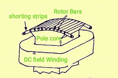
In order to eliminate hunting and to develop the necessary starting torque when A.C. voltage is applied to the stator, the rotor poles contain pole-face conductors which are short-circuited at their ends as shown in below image


This a mortises or damper winding consists of solid copper bars embedded at the surface
of the pole face and short-circuited at each end by means of a shorting strip as shown in below image.


The field circuit leads are brought out to two slip rings mounted on the rotor shaft.

Carbon brushes mounted in brush holders make contact with the two slip rings.

The terminals of the field circuit are brought out from the brush holders to a second terminal
box mounted on the motor frame. 

What parts are the main for synchronous machine?


There are two main parts of the synchronous motor stator and rotor. The stator is the stationary part and rotor is the rotating part. The three-phase AC supply is given to the stator of the motor.

What is Motor Converter? And How it works?

What is Motor Converter? And How it works?

Motor Converter :

An induction motor and a synchronous converters are on a common shaft with their rotor windings in series with each other is called inverter.

Motor converter are required more in industries and in many manufacturing company, so basic knowledge of motor converters required, which is provided below.


What is Motor Converter? And How it works?

Motor Converter


A motor converter essentially consists of an ordinary slip-ring induction motor coupled both mechanically and electrically to a D.C. generator.


The rotor of the induction motor is usually wound for 12 phases to obtain better performance.


A.C. voltage up to 11 kV can be directly fed to the stator.


If A.C. voltage available is more than 11 kV then it is economical to step down the voltage before feeding it to the stator winding.


The rotor of the slip-ring induction motor is mechanically as well as electrically coupled to D.C. generator.


D.C. generator is also known as armature of the converter.


The motor input energy is partly transmitted mechanically(through the shaft)and partly electrically, i.e., as slip ring energy from the rotor of the induction motor.


Advantages Of Motor Converter


✓It is self starting.

✓The set is simple to operate and is reliable.

✓It has sufficiently high power factor.

✓It permits wide regulation in D.C. voltage.

✓It can be operated on any frequency.

✓It can be operated at high voltages.


Disadvantages of Motor Converter


✓Because of its low speed, it is more expensive and hence it is not much popular.


✓It is possible to obtain D.C. voltage up to 1700-2000 V.

✓Low overload capacity.

✓Low power factor.

So, in this article we learn about what is motor converter, How motor converter works and advantage, disadvantages of converter. I hope this article will help. Thank You !!


Transformer Noise and Techniques of Reduce Transformer Noise

Transformer Noise and Techniques of Reduce Transformer Noise


There are many losses are occurred in the transformer, so by this losses and friction, Noise will be produced and which spread the noise pollution in environment.

Transformer Noise and Techniques of Reduce Transformer Noise


So, How noise will be occurs and prevent of noise is provided below in detail.


Transformer Noise


The “hum” noise sound caused by energized power transformer, under no-load conditions, originates in the core where the laminations tend to vibrate by muriatic forces.


The noise is transmitted through the oil to the tank side and thence to the surroundings.


There are the main factors which produce noise in transformers:


‌Magnetostriction (occurrence of dimensional changes both parallel to, and perpendicular to the direction of magnetization).


‌The mechanical vibrations caused by the laminations, depending upon the tightness
of clamping, size, gauge, associated structural parts, etc.


‌The mechanical vibration of tank walls.


‌The damping.


The noise produced by Transformer may be reduced by the following methods/means:


‌Prevention of vibration of core-plate by the use of a lower flux density and giving attention to constructional feature(such as clamping bolts, proportions and dimensions of the 'steps' in plate width, tightness of clamping and uniformity of plates).


‌Using cushions, padding, or oil barriers to sound insulate the transformer from tank.


‌Designing suitably the tank and stiffeners to check tank wall vibration.


‌Sound insulating the tank from the ground or surrounding air.


Perfectly noise problem cannot be solved. completely.


Difference between Induction Motor and Synchronous Motor

Difference between Induction Motor and Synchronous Motor

Induction Motor :


An induction motor is also known as an asynchronous motor. It is a mostly used in AC electric motor. In this type of induction motor, the current in the rotor needed to produce torque is obtained via electromagnetic induction from the rotating magnetic field of the stator winding. 

Synchronous Motor :


Synchronous Motor is the motor in which the speed of the rotor of the motor is the same as the rotating magnetic field.

There many differences between Induction Motor and Synchronous Motor which all are the differences are provided below which is more helpful to choose any one of them easily.


Difference between Induction Motor and Synchronous Motor


Difference Point 1


Induction Motor: Does not require D.C. excitation.

Synchronous Motor: Requires D.C. excitation.


Difference Point 2


Induction Motor: Speed can be controlled but to small extent.

Synchronous Motor: Speed control not possible.


Difference Point 3


Induction Motor: Its speed falls with the increase in load and is always less than synchronous speed.

Synchronous Motor: Its average speed is constant and independent of load.


Difference Point 4


Induction Motor: It operates at only lagging power factor, which becomes very poor at light loads.

Synchronous Motor: Its torque is less sensitive to change in supply voltage.


Difference Point 5


Induction Motor: Its torque is more sensitive to change in supply voltage.

Synchronous Motor: Its torque is less sensitive to change in supply voltage.


Difference Point 6


Induction Motor: Breakdown torque is proportional to the square of the supply voltage.

Synchronous Motor: Breakdown torque is proportional to the supply voltage.


Difference Point 7


Induction Motor: More simple and less costly comparatively.

Synchronous Motor: More complicated and more costly comparatively.


Difference Point 8


Induction Motor: Employed for supplying mechanical load only.

Synchronous Motor: Employed for supplying mechanical load as well as for power factor improvement.